PHYS:3850
Electronics
Dept. of Physics
& Astronomy,
The Univ. of Iowa
John A. Goree
512 VAN
phone 335-1843
last updated 23 Jan 2020
Lecture
Tu We 1:30-4:30, 561 VAN
- begins the first week of classes
- bring a notebook and manual
- read the manual before lab
- An introductory physics course covering electricity and magnetism.
- Familiarity with complex numbers and some calculus.
To train science students, both undergraduate and graduate, to:
- build small practical circuits
- make electronic measurements
- program standard laboratory software
This course is suitable for students in all science departments. It is not intended solely for Physics and Astronomy students.
The laboratory is the focus of the learning experience in this course.
The lecture:
- serves primarily to prepare students for the laboratory.
- uses active learning, with a flipped classroom and peer instruction.
Homework:
- is not a central part of the course
- uses less math than most 100 level physics courses
- some HW is intended to supplement the lab learning experience
Syllabus 2020
Current files are available on ICON:
- Syllabus
- Grading policy
- Schedule
- Homework assignments
- Available on ICON: Lab
Manual-- approx 160 pages
- Scanned lecture notes
- Available on ICON: Example lab reports
handheld multimeter:

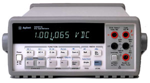
benchtop multimeter:
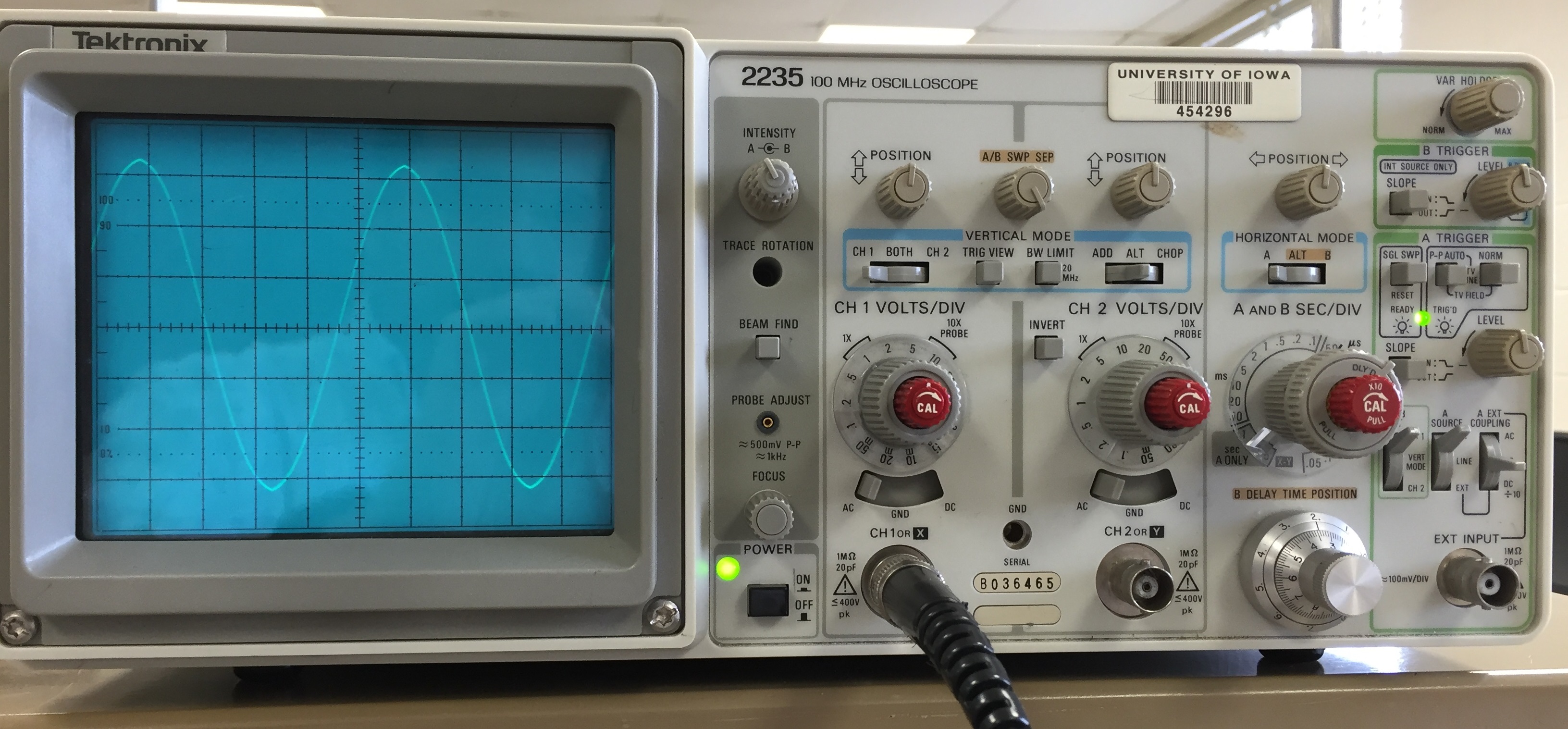
analog oscilloscope:
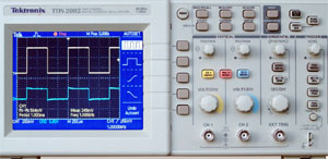
digital oscilloscope:
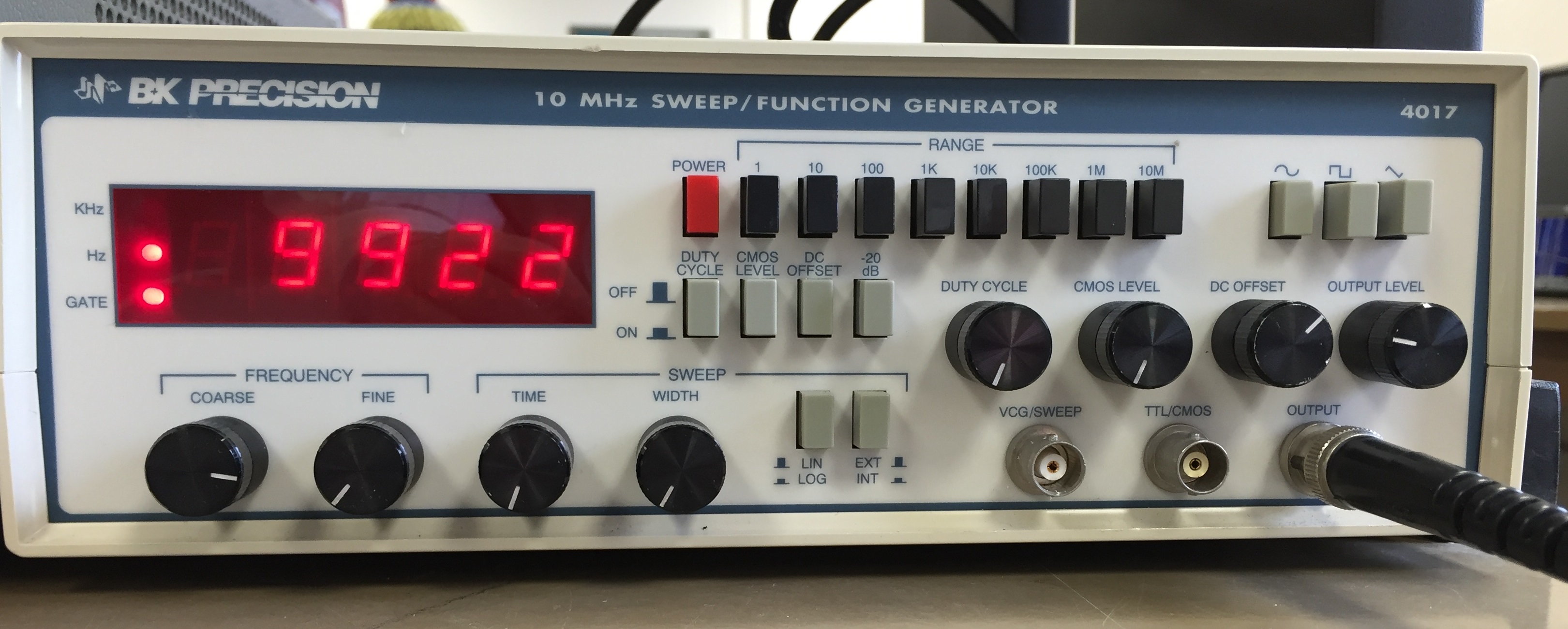
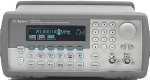
function generator:
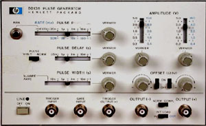
pulse generator:
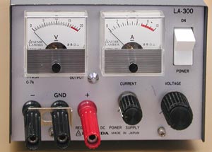
bench power supply:
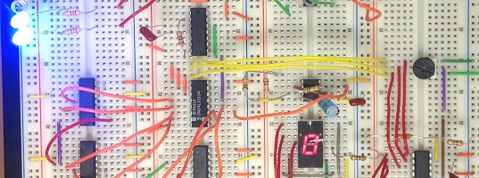
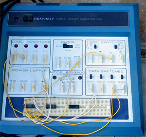
prototyping board:
(Use the following as a checklist when studying for exams):
- voltage divider
- current source (several kinds)
- passive low-pass filter
- passive high-pass filter
- passive rectifier, half-wave & full-wave
- power supply
- diode limiter
- diode clamp
- emitter follower
- transistor switch
- transistor current source
- common-emitter amplifier
- op-amp voltage amplifier
- op-amp summing amplifier
- op-amp difference amplifier
- op-amp low-pass filter
- op-amp high-pass filter
- op-amp active rectifier
- phototransistor light detector
- comparator
digital:
- gate circuits
- flip-flop circuits
- shift register
- counters
- LED display driver
- switch debouncing
analog/digital:
- oscillator
- one-shot
- digital-to-analog conversion
complications of circuits
- loading of output (voltage source)
- compliance voltage (current source)
- reflected signals (RF)
(Use the following as a checklist when studying for exams):
- continuity
- dc voltage
- ac voltage
- dc current
- resistance
- frequency
- triggering
- rise time
- phase response
- frequency response
- dc vs. ac input coupling
- voltage regulator stiffness
- amplifier gain
- common-mode rejection ratio
- input impedance
- output impedance
- amplifier saturation
- timing diagrams
- transient events
- clocking
- digitizing resolution
You will learn to use:
- Labview (data acquisition and control software)
- Multisym (SPICE-based circuit-simulation software)
You will design and build a circuit of your own to meet whatever purpose you like:
- Toward the end of the semester, there will be no lectures and no regular lab exercises, in order to allow time for this project.
- At the beginning, you will give a 5-minute presentation in class on your proposed project. At the end, you will demonstrate your circuit.
- The circuit could arise from a hobby, a game, thesis project, or anything from your own imagination.
- Your design must be your own.
- More instructions are found in the back of the lab manual.
-
Project examples:
- Actual student projects:
- grade 95+% This prototype-board project is more ambitious than average, with significant creativity and variety. The circuit has a good error-free design and the entire circuit worked when demonstrated. The schematic is complete and fully labeled. The specifications (not shown here) were complete. The student was able to explain every feature of the design.
- grade 80% This prototype-board project was average in its complexity and variety. There are no significant design errors. The entire circuit worked when demonstrated. The specifications (page 2) are complete and ok. The schematic is properly labeled. The student was able to explain most features of the design, but was a little fuzzy on portions of the schematic (because some of the ideas incorporated in the design came from the TA, and some came from the textbook, without the student fulling understanding these ideas, although the student did properly disclose these elements)
- grade 60% This prototype-board project was average in complexity. The circuit has serious design errors such as: outputs of two chips connected at a node, elements of the circuit that are randomly connected or unnecessary, and the overall design doesn't make sense. The schematic and specifications are incomplete.
- Photos of all student projects from 2013
- Actual student projects: